KYB and Showa Shock Service and Race Tech Gold and
Delta Valve Installation.
By Doug Jenks
Directions- Use a Showa or KYB shock to perform the following work sheet. If you are not installing Race Tech gold or Delta Valves some steps can be skipped.
1. Remove the shock from the bike and clean it thoroughly.
2. Measure the installed spring length before removing the spring, fig 1. This will allow you to reinstall the spring close to the original sag if using the same spring.
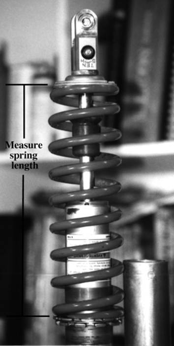
Fig 1
My installed spring length is
__________
3. Screw both the compression and rebound adjusters in while counting how many clicks you hear.
My low speed compression adjuster is __________ turns out.
My high speed compression adjuster is __________ turns out (if installed).
My rebound adjuster is __________ turns out.
4. Turn the compression and rebound adjusters all the way out.
5. Clamp the shock in a padded vice and push down the nitrogen valve core to remove all of the nitrogen from the bladder. Remove the valve core.
6. Use a deep well socket and press the bladder cap down until the circlip is exposed, fig 2. Remove the circlip with a small screwdriver and then remove the bladder cap, fig 3.
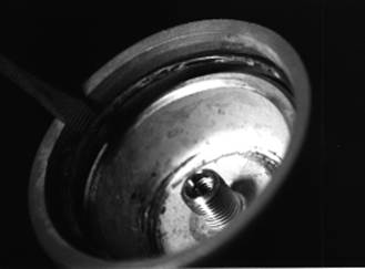
Fig 2
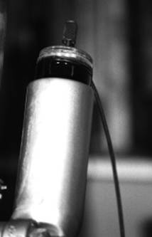
Fig 3
7. Pour out the old shock oil through the reservoir.
8. Use a punch and tap the shock body end cap up until it is free, fig 4. Tap the cap off evenly.
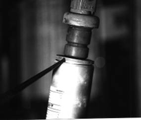
Fig 4
9. Push the seal head assembly down until the circlip is exposed, fig 5. Remove the circlip. Race Tech's seal head tool makes this job easier.
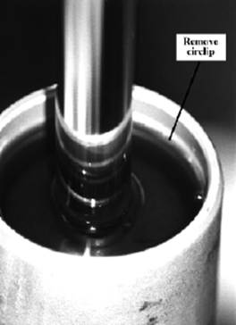
Fig 5
10. Remove the shaft assembly by gently tapping up on the shaft assembly eyelet with a plastic mallet. After the shaft assembly is removed poor out any old oil that is still in the shock body.
11. Clean the shock body and shaft assembly with solvent and let it dry. If you are only changing oil you can go to STEP 34. If you are installing the Gold Valve kit or changing the seal you can continue onto step 12.
Caution: The next step is very critical and should be done by a qualified suspension specialist. Do not do it if you do not understand it.
12. Grind off the peening at the end of the shaft assembly. Fig. 6 shows the correct way to grind this off. When grinding off the peening only grind off enough of the peen to remove the nut. On Showa shocks do not remove the peening that holds the rebound adjustments in. Leave enough of the nut to get a wrench on it.
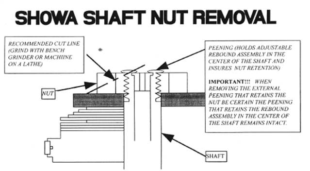
Fig 6
13. Remove the nut and clean up the threads on the shaft. Slightly chamfer the end of the shaft and inspect the threads.
14. Remove the valve stack and lay it out in the exact order it came off. A piece of bent wire can be used to keep the stack in order.
15. Clean the shaft assembly and blow out the rebound hole with compressed air.
16. Inspect the shock seal, shaft bushing, bottom out bumper, and o-rings. Inspect the shock shaft for wear or missing chrome. If the shaft is worn it can be re chromed by Race Tech. All worn parts can be bought from Race Tech.
17. Install the spring retainer, bottom out bumper, shock body end cap, and shock seal assembly, fig 7.
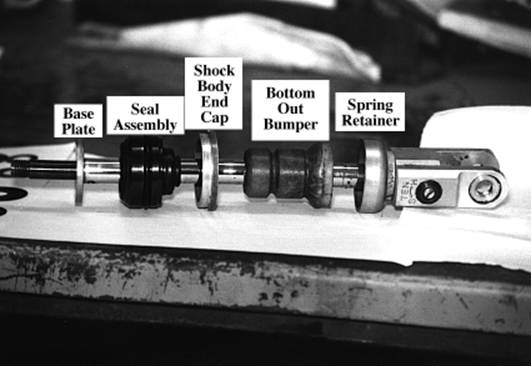
Fig 7
18. Surface the base plate by sanding it using 320 sandpaper taped to a piece of glass. Install the base plate.
Note: Some shocks use a base plate washer that goes on before the base plate.
19. Contact Race Tech for your valving settings. Fig. 8 shows a typical valve stack. Once you have the settings you can assemble the high speed compression stack using the valving chart supplied with the Gold Valves. Start with the small diameter shim against the base plate.Next install the mid-speed compression stack (if used) starting with the smallest diameter. Then install the low speed compression stack starting with the smallest diameter shim and ending with the 38 mm diameter shim that will go against the Gold Valve. Clean all shims with contact cleaner before installing to make sure there is no dirt on them.
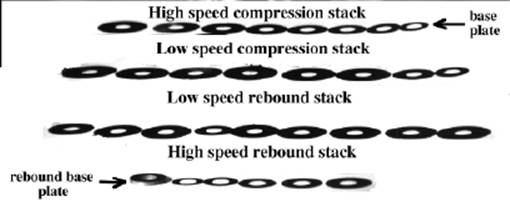
Fig 8
20. If your shock needs the bleed hole drilled (some do not need this) determine what size drilled is needed. Race Tech will tell you what size drill is needed. To drill the jet, install it into the Gold Valve and drill from the pre-drilled side. Remove the jet, de-burr and clean it. Reinstall it using blue Loctite. If Race Tech says "N/A" for the bleed hole you do not need to drill it. In this case install the jet using blue Loctite and it will act as a plug, fig 9.
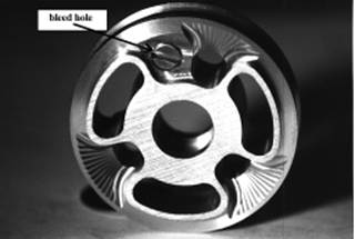
Fig 9
21. Inspect the Gold Valve for burrs and surface the Gold Valve using 320 sandpaper on a piece of glass. Anytime the Gold Valve is removed it should be surfaced.
22. Install the Gold Valve on the shaft with the large ports facing down towards the compression stack. The bleed jet will also face towards the compression stack.
23. Select the rebound valving stacks.
24. Install the low speed rebound stack with the 34 mm diameter shim against the Gold Valve face. Next install the high speed stack starting with the 34 mm diameter shim and ending with the smallest shim. If the low speed stack is not needed (according to Race Tech), only install the high speed stack.
Caution: The next step is critical. If you do not understand it contact Race Tech for more information.
25. The total valve stack thickness must be adjusted so the rebound base
plate (thick washer) must be above the lip on the shaft, fig 10. The
rebound clamping shim (the last shim installed before the rebound base plate)
must also be installed below the same lip.
If the valve stack needs to be moved up you can use shims that are LARGER in
diameter that the rebound clamping shim, fig 11.
Flat washers that are larger in diameter than the rebound clamping shim can
also be used to achieve the correct clearance.
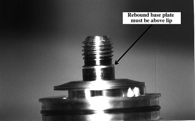
Fig 10
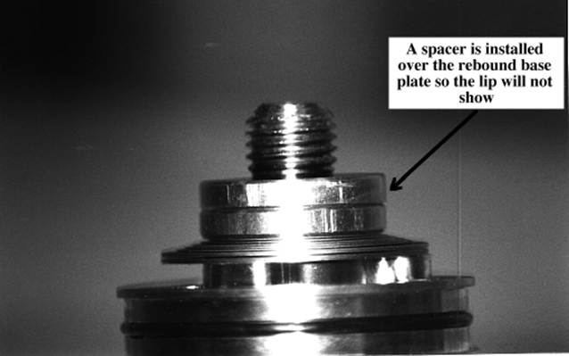
Fig 11
Note: Plugged end KYB' s need the check valve disabled. Call Race Tech for support. Some bikes with this is 89 YZ 125/250, 89 91 CR 125, 91 CR 250/500
26. Use a metric thread pitch gage and check the thread pitch on the shock shaft. KYB usually uses a 12 x 1.5mm thread while Showa usually uses a 12 X 1.25 mm thread. The Gold Valve kit comes with two nuts. The right pitch nut must be used. If you have any questions contact a suspension specialist or Race Tech.
27. Clean the threads and install the nut with red Loctite. Torque the nut to 24 ft/lbs.
28. Hold the shaft assembly up to the light and look at the valve stack. Check for dirt in the stack,and that the shims are sitting flat against the Gold Valve assembly. Check the crossover gaps between the low and high speed stacks. If there are any problems disassemble the stack and look for burrs or dirt on the Gold Valve or shims.
29. Install the o-ring that is supplied with the kit around the outside of the Gold Valve. Do not use the stock o-ring. Make sure the o-ring sits all the way down into the groove.
30. Install the new ring around the outside of the Gold Valve.
31. If you are installing a Race Tech Delta valve or you need to remove the compression damper adjuster from the shock you will have to drill out the peening from around the threads, fig 12. Use a 1/8 inch (3 mm) drill bit and carefully drill out the punch marks. Drill into the punch marks about .080 inch (2 mm). Remove the compression adjuster assembly.
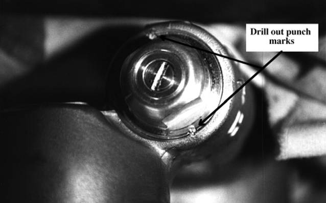
Fig 12
32. Inspect the Delta Valve assembly and make sure the internal damping mechanism hasn't slid out. If it has, hold it vertically, line it up, and slide it back together.
33. Install the Delta Valve or stock compression adjuster with blue Loctite. Torque it to 35 ft/lbs.
34. Clamp the shock body in a padded vice. Pour shock oil in the reservoir until it's about an inch (25 mm) from the top.
35. Install the air valve in the bladder and install the bladder into the reservoir. Oil should overflow as the bladder is pushed in. Push the bladder down far enough so the circlip can be put in and install the circlip in the groove.
36. Pressurize the bladder with 40 PSI of air. The air will inflate the bladder and push oil through the compression adjuster.
37. Fill the shock body within one inch (25mm) from the top. While holding the piston ring in place, install the shock shaft assembly into the body. The shaft should go in smoothly. If it does not, the o-ring may not be correct. Call a suspension specialist.
38. The air must be removed from the shock assembly before final assembly. To bleed the air, push down on the shock quickly and then pull it back up slowly. Forcing the shock down fast will open the valving and force the air out. Continue doing this until there is no more air bubbles coming out.
39. Once the air has been bled, extend the shaft almost out making sure the rebound hole does not suck air. If you hear a sucking noise you extended it too far and you will have to start the bleeding procedure all over.
40. Fill the shock body with oil and push the seal head down. Oil will overflow from the shock. Once the o ring on the seal head has sealed on the shock body, push in the reservoir valve core while still pushing down on the seal head. Push the seal head into the shock body until the circlip groove is seen. Install the circlip.
41. Pressurize the reservoir with 20 PSI of air to seat the seal head. Make sure the seal head is installed properly and the circlip is holding it into place. Let out any air that is in the bladder.
42. Tap the end cap on with a plastic hammer.
43. Pressurize the shock to 175 PSI with nitrogen.
Caution:
Air should never be used in shocks since it will expand with heat and could
cause excessive pressures in the shock.
44. Push the shaft down and watch how it goes back up on it's own. It should not stop or hesitate on the upstroke. It should extent itself all the way out. A properly working shock will return smoothly. If there are any problems, disassemble the shock and inspect for problems. If there is air in the shock it could cause some of these problems.
45. Install the spring and retainer. Adjust the spring tension to your install free length from step 2.
46. Set the compression and rebound adjusters to either Race Tech's recommendations or to within the settings from step 3.